
 0
0


 italiano
 Polskie
 Nederlands
 Deutsch
 Français
 Español
 Український
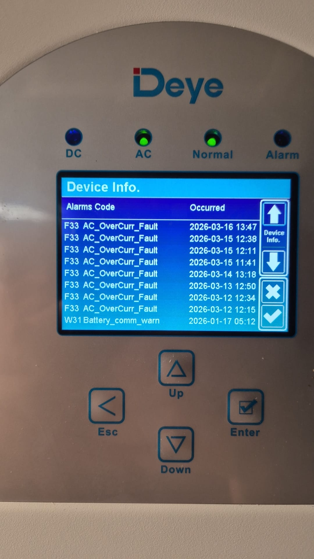
Home / News & Events / Industry News / F33 Is Not Always a "False Alarm": Why Phase Current, AC Coupling and Transient Loads Matter
-
 FAST SHIPPING
-
 COMPETITIVE PRICE
-
 EXCELLENT AFTER-SERVICE
 Lithium Battery 100AH, 6.1KWh, IP21")


